
Overview
Hi all, welcome back to another blog post on Ansible. I hope most of you are familiar with spine and leaf architecture, where each leaf switch connects to every spine switch to create a non-blocking, scalable fabric. In this example, we will have two spine switches and six leaf switches, and each leaf switch connects to both spines. Our goal here is to use Ansible to fully manage the configurations, making adding more leaf switches as easy as updating a simple YAML file.
If you are not familiar with spine-leaf topology, don't worry. This is more of an Ansible tutorial, and you can apply the knowledge to various topologies. So, let's get to it.
Diagram and Initial Setup
The configuration in this example is based on the diagram below. As mentioned, each leaf switch connects to both spine switches, creating a fully connected fabric.
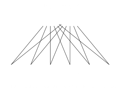
All the links between the switches are Layer 3 point-to-point links, and we will place all of these interfaces into OSPF Area 0. For this lab, we will be using Arista switches running the EOS operating system.
- On every leaf switch,
Ethernet1connects tospine-01andEthernet2connects tospine-02. - On the spine switches, the connections correspond to the leaf number:
Ethernet1connects toleaf-01,Ethernet2connects toleaf-02, and so on.
For IP addressing, each device will have a Loopback0 interface, and the scheme is as follows:
- spine-01:
192.168.10.11/32 - spine-02:
192.168.10.12/32 - leaf-01:
192.168.10.21/32 - leaf-02:
192.168.10.22/32(and so on)
Instead of assigning unique IP subnets to every link, we will use ip address unnumbered on all physical interfaces, pointing to the device's own loopback interface.
Target Configuration
Below is the target configuration we want to achieve on all our switches. As you will see, the configuration for the devices is nearly identical, with the only significant differences being the IP addresses and the interface descriptions.
Spine Switch Example (spine-01)
ip routing
!
router ospf 1
!
interface Loopback0
   ip address 192.168.10.11/32
   ip ospf area 0.0.0.0
!
interface Ethernet1
   description Link to Leaf-01
   mtu 9214
   no switchport
   ip address unnumbered Loopback0
   ip ospf network point-to-point
   ip ospf area 0.0.0.0
!
interface Ethernet2
   description Link to Leaf-02
   mtu 9214
   no switchport
   ip address unnumbered Loopback0
   ip ospf network point-to-point
   ip ospf area 0.0.0.0
!
...and so on, for all six leaf switches.
Leaf Switch Example (leaf-01)
ip routing
!
router ospf 1
!
interface Loopback0
   ip address 192.168.10.21/32
   ip ospf area 0.0.0.0
!
interface Ethernet1
   description link to spine-01
   mtu 9214
   no switchport
   ip address unnumbered Loopback0
   ip ospf network point-to-point
   ip ospf area 0.0.0.0
!
interface Ethernet2
   description link to spine-02
   mtu 9214
   no switchport
   ip address unnumbered Loopback0
   ip ospf network point-to-point
   ip ospf area 0.0.0.0
!
Our goal is to write an Ansible playbook that can generate this entire configuration for all devices automatically.
What is Ansible?
Ansible is open-source software that automates software provisioning, configuration management, and application deployment, based on an agentless architecture. Hosts are managed by an Ansible control machine via SSH. When it comes to network automation, Ansible supports a large range of vendors such as Cisco, Arista, Juniper, Palo Alto, Fortigate and many more.
Ansible is simple to use, easy to understand, and widely supported across the industry. Many network vendors provide official Ansible modules and collections, along with plenty of documentation and examples to help you get started.
Installing Ansible with pip
For this lab, let’s use a Python virtual environment so that everything stays isolated. A virtual environment (venv) allows you to install Python packages in a local directory, separate from the system-wide packages. This is useful when you want to avoid version conflicts or keep your setup clean. First, create a virtual environment, activate it and then install Ansible using pip.
python3 -m venv venv
source venv/bin/activate

pip install ansible
Ansible Components
At a high level, there are a few files and folders that you'll see in almost every Ansible project. The ansible.cfg file lets you set some defaults like where your inventory is or how Ansible connects to devices. The inventory file is just a list of devices you want to manage, usually grouped based on function.
You also have a group_vars directory where you can define variables for your device groups. And finally, the playbook is where you define the actual tasks you want Ansible to run. Everything we do in this lab will be tied together through the playbook.
Our example is based on the following directory structure. So, let's look at each file and directory and what purpose it serves.
.
├── ansible.cfg
├── data.yml
├── inventory
│   ├── group_vars
│   │   └── arista-switches.yml
│   ├── host_vars
│   └── hostfile.yml
├── pb_push_config.yml
├── pb_test_ospf.yml
ansible.cfg
[defaults]
host_key_checking = False
inventory = inventory/hostfile.yml
The ansible.cfg file sets some basic defaults. Here we are disabling SSH host key checking and pointing Ansible to our inventory file.
inventory/hostfile.yml
The hostfile.yml defines all the devices we want to manage. We’ve grouped everything under arista-switches, which is further split into spine and leaf.
all:
 children:
   arista-switches:
     children:
       spine:
         hosts:
           spine-01:
             ansible_host: 192.168.100.11
           spine-02:
             ansible_host: 192.168.100.12
       leaf:
         hosts:
           leaf-01:
             ansible_host: 192.168.100.21
           leaf-02:
             ansible_host: 192.168.100.22
           leaf-03:
             ansible_host: 192.168.100.23
           leaf-04:
             ansible_host: 192.168.100.24
           leaf-05:
             ansible_host: 192.168.100.25
           leaf-06:
             ansible_host: 192.168.100.26
This makes it easier to run tasks on specific groups, like all spine switches or all leaf switches. Each device has a hostname and its management IP defined using ansible_host.
group_vars/arista-switches.yml
The file group_vars/arista-switches.yml contains variables that apply to all devices in the arista-switches group.
---
ansible_connection: ansible.netcommon.network_cli
ansible_network_os: arista.eos.eos
ansible_become: yes
ansible_become_method: enable
ansible_user: admin
ansible_password: admin
ansible_become_password: admin
Since the filename matches the group name in the inventory, Ansible automatically applies these settings to every device in that group. These variables tell Ansible how to connect to the devices and which platform they use. This way, you don’t have to repeat these settings for each device.
Note - In a real production environment, you should never store plain text credentials in your files. Always use secure methods like Ansible Vault to encrypt sensitive information such as passwords and API tokens.
data.yml
The data.yml file holds all the device-specific details we need to build the configurations. Each switch is defined as a top-level key, and under that, we specify its loopback IP and a list of interfaces with descriptions.
---
leaf-01:
 loopback0: 192.168.10.21/32
 interfaces:
   - name: Ethernet1
     description: "link to spine-01"
   - name: Ethernet2
     description: "link to spine-02"
leaf-02:
 loopback0: 192.168.10.22/32
 interfaces:
   - name: Ethernet1
     description: "link to spine-01"
   - name: Ethernet2
     description: "link to spine-02"
leaf-03:
 loopback0: 192.168.10.23/32
 interfaces:
   - name: Ethernet1
     description: "link to spine-01"
   - name: Ethernet2
     description: "link to spine-02"
leaf-04:
 loopback0: 192.168.10.24/32
 interfaces:
   - name: Ethernet1
     description: "link to spine-01"
   - name: Ethernet2
     description: "link to spine-02"
leaf-05:
 loopback0: 192.168.10.25/32
 interfaces:
   - name: Ethernet1
     description: "link to spine-01"
   - name: Ethernet2
     description: "link to spine-02"
leaf-06:
 loopback0: 192.168.10.26/32
 interfaces:
   - name: Ethernet1
     description: "link to spine-01"
   - name: Ethernet2
     description: "link to spine-02"

spine-01:
 loopback0: 192.168.10.11/32
 interfaces:
   - name: Ethernet1
     description: "Link to Leaf-01"
   - name: Ethernet2
     description: "Link to Leaf-02"
   - name: Ethernet3
     description: "Link to Leaf-03"
   - name: Ethernet4
     description: "Link to Leaf-04"
   - name: Ethernet5
     description: "Link to Leaf-05"
   - name: Ethernet6
     description: "Link to Leaf-06"
spine-02:
 loopback0: 192.168.10.12/32
 interfaces:
   - name: Ethernet1
     description: "Link to Leaf-01"
   - name: Ethernet2
     description: "Link to Leaf-02"
   - name: Ethernet3
     description: "Link to Leaf-03"
   - name: Ethernet4
     description: "Link to Leaf-04"
   - name: Ethernet5
     description: "Link to Leaf-05"
   - name: Ethernet6
     description: "Link to Leaf-06"
This structure keeps everything clean and easy to read. Since most of the configuration is similar across devices, the main difference is the interface names and descriptions. By storing this data separately, we can write a generic playbook that reads from this file and builds the correct config for each device. This approach also makes it easier to add or update devices later without touching the playbook logic.
pb_push_config.yml
This playbook is responsible for configuring all the switches in our spine-leaf fabric. It reads device-specific data from a separate file and applies a consistent set of configurations across the devices. The idea is to keep the logic generic while letting the data drive the actual config for each device.
---
- name: Arista Spine-Leaf Configuration
 hosts: arista-switches
 gather_facts: false
 tasks:
   - name: Load variables from file
     ansible.builtin.include_vars:
       file: data.yml
       name: data
     run_once: true

   - name: Enable IP routing
     arista.eos.eos_config:
       lines: ip routing

   - name: Enable OSPF
     arista.eos.eos_ospfv2:
       config:
         processes:
           - process_id: 1

   - name: Configure Loopback0 Interface
     arista.eos.eos_l3_interfaces:
       config:
         - name: Loopback0
           ipv4:
             - address: "{{ data[inventory_hostname]['loopback0'] }}"

   - name: Configure All Physical Interfaces
     arista.eos.eos_interfaces:
       config:
         - name: "{{ item.name }}"
           description: "{{ item.description | default(omit) }}"
           enabled: true
           mode: layer3
           mtu: 9214
     loop: "{{ data[inventory_hostname].interfaces }}"
     loop_control:
       label: "{{ item.name }}"

   - name: Apply IP Unnumbered to all physical interfaces
     arista.eos.eos_config:
       lines:
         - ip address unnumbered Loopback0
       parents: "interface {{ item.name }}"
     loop: "{{ data[inventory_hostname].interfaces }}"
     loop_control:
       label: "{{ item.name }}"

   - name: OSPF Interface Configuration
     arista.eos.eos_ospf_interfaces:
       config:
         - name: "{{ item.name }}"
           address_family:
             - afi: "ipv4"
               area:
                 area_id: "0.0.0.0"
               network: "point-to-point"
     loop: "{{ data[inventory_hostname].interfaces }}"
     loop_control:
       label: "{{ item.name }}"

   - name: OSPF Loopback Configuration
     arista.eos.eos_ospf_interfaces:
       config:
         - name: Loopback0
           address_family:
             - afi: "ipv4"
               area:
                 area_id: "0.0.0.0"
Here’s a breakdown of what each section in pb_push_config.yml does.
Playbook Header
- name: Arista Spine-Leaf Configuration
  hosts: arista-switches
  gather_facts: false
This defines the playbook and says it should run on all devices in the arista-switches group. We don’t need to gather any facts, so gather_facts is set to false.
Load Variables from File
- name: Load variables from file
  ansible.builtin.include_vars:
    file: data.yml
    name: data
  run_once: true
This loads all the device-specific data from data.yml into a variable named data, which we’ll use throughout the playbook. You can use the run_once: true directive in your task to ensure it only runs once, even if the play is targeting multiple hosts.
Enable IP Routing
- name: Enable IP routing
  arista.eos.eos_config:
    lines: ip routing
This ensures that IP routing is enabled on all switches. We are just using the generic CLI command for this, as there is no separate module available for this.
Enable OSPF Process
- name: Enable OSPF
  arista.eos.eos_ospfv2:
    config:
      processes:
        - process_id: 1
This configures OSPF process ID 1. This is the CLI equivalent to router ospf 1
Configure Loopback Interface
- name: Configure Loopback0 Interface
  arista.eos.eos_l3_interfaces:
    config:
      - name: Loopback0
        ipv4:
          - address: "{{ data[inventory_hostname]['loopback0'] }}"
Each device gets a unique loopback IP address pulled from data.yml.
address: "{{ data[inventory_hostname]['loopback0'] }}" tells Ansible to look up the current device's name (inventory_hostname) in data.yml and fetch the value under the loopback0 key. So, for example, if the device is leaf-03, it picks 192.168.10.23/32 from the data file..
Configure All Physical Interfaces
- name: Configure All Physical Interfaces
  arista.eos.eos_interfaces:
    config:
      - name: "{{ item.name }}"
        description: "{{ item.description | default(omit) }}"
        enabled: true
        mode: layer3
        mtu: 9214
  loop: "{{ data[inventory_hostname].interfaces }}"
This configures all the Ethernet interfaces based on the list in data.yml. It enables them, sets the MTU, and puts them in Layer 3 mode. The default(omit) part means that if the description is not defined for an interface, Ansible will skip setting that field entirely.
Apply IP Unnumbered to Physical Interfaces
- name: Apply IP Unnumbered to all physical interfaces
  arista.eos.eos_config:
    lines:
      - ip address unnumbered Loopback0
    parents: "interface {{ item.name }}"
  loop: "{{ data[inventory_hostname].interfaces }}"
Instead of assigning unique IPs, each interface borrows the loopback IP using ip address unnumbered. Similar to enabling IP routing, there's no dedicated module to configure ip address unnumbered, so we're using the generic arista.eos.eos_config module for this part.
OSPF Interface Configuration
- name: OSPF Interface Configuration
  arista.eos.eos_ospf_interfaces:
    config:
      - name: "{{ item.name }}"
        address_family:
          - afi: "ipv4"
            area:
              area_id: "0.0.0.0"
            network: "point-to-point"
  loop: "{{ data[inventory_hostname].interfaces }}"
Adds each physical interface to OSPF Area 0 and marks them as point-to-point.
OSPF Loopback Configuration
- name: OSPF Loopback Configuration
  arista.eos.eos_ospf_interfaces:
    config:
      - name: Loopback0
        address_family:
          - afi: "ipv4"
            area:
              area_id: "0.0.0.0"
Finally, this ensures the loopback interface is also advertised into OSPF Area 0.
Testing and Verifications
Let’s run the playbook using the ansible-playbook pb_push_config.yml command. It should run all the tasks and configure the devices. It may take a minute or two to complete.
(venv) ➜  leaf-spine-ansible git:(main) ✗ ansible-playbook pb_push_config.yml

PLAY [Arista Spine-Leaf Configuration] ***************************************************************************************

TASK [Load variables from file] **********************************************************************************************
ok: [spine-01]

TASK [Enable IP routing] *****************************************************************************************************
changed: [leaf-01]
changed: [spine-01]
changed: [spine-02]
changed: [leaf-02]
changed: [leaf-03]
changed: [leaf-05]
changed: [leaf-04]
changed: [leaf-06]

TASK [Enable OSPF] *********************************************************************************************************
changed: [leaf-02]
changed: [leaf-01]
changed: [spine-01]
changed: [spine-02]
changed: [leaf-03]
changed: [leaf-06]
changed: [leaf-04]
changed: [leaf-05]

TASK [Configure Loopback0 Interface] **************************************************************************************
changed: [leaf-01]
changed: [leaf-02]
changed: [leaf-03]
changed: [spine-02]
changed: [spine-01]
changed: [leaf-06]
changed: [leaf-05]
changed: [leaf-04]

TASK [Configure All Physical Interfaces] *********************************************************************************
changed: [spine-01] => (item=Ethernet1)
changed: [leaf-01] => (item=Ethernet1)
changed: [leaf-02] => (item=Ethernet1)
changed: [spine-02] => (item=Ethernet1)
changed: [leaf-03] => (item=Ethernet1)
changed: [spine-01] => (item=Ethernet2)
changed: [leaf-02] => (item=Ethernet2)
changed: [leaf-03] => (item=Ethernet2)
changed: [spine-02] => (item=Ethernet2)
changed: [leaf-01] => (item=Ethernet2)
changed: [spine-01] => (item=Ethernet3)
changed: [spine-02] => (item=Ethernet3)
changed: [leaf-04] => (item=Ethernet1)
changed: [leaf-06] => (item=Ethernet1)
changed: [leaf-05] => (item=Ethernet1)
changed: [spine-01] => (item=Ethernet4)
changed: [spine-02] => (item=Ethernet4)
changed: [leaf-06] => (item=Ethernet2)
changed: [leaf-05] => (item=Ethernet2)
changed: [leaf-04] => (item=Ethernet2)
changed: [spine-01] => (item=Ethernet5)
changed: [spine-02] => (item=Ethernet5)
changed: [spine-01] => (item=Ethernet6)
changed: [spine-02] => (item=Ethernet6)

TASK [Apply IP Unnumbered to all physical interfaces] *********************************************************************
changed: [spine-01] => (item=Ethernet1)
changed: [leaf-01] => (item=Ethernet1)
changed: [leaf-03] => (item=Ethernet1)
changed: [leaf-02] => (item=Ethernet1)
changed: [spine-02] => (item=Ethernet1)
changed: [spine-02] => (item=Ethernet2)
changed: [leaf-02] => (item=Ethernet2)
changed: [leaf-03] => (item=Ethernet2)
changed: [leaf-01] => (item=Ethernet2)
changed: [spine-01] => (item=Ethernet2)
changed: [spine-02] => (item=Ethernet3)
changed: [spine-01] => (item=Ethernet3)
changed: [leaf-05] => (item=Ethernet1)
changed: [leaf-06] => (item=Ethernet1)
changed: [leaf-04] => (item=Ethernet1)
changed: [spine-02] => (item=Ethernet4)
changed: [spine-01] => (item=Ethernet4)
changed: [leaf-05] => (item=Ethernet2)
changed: [leaf-04] => (item=Ethernet2)
changed: [leaf-06] => (item=Ethernet2)
changed: [spine-02] => (item=Ethernet5)
changed: [spine-01] => (item=Ethernet5)
changed: [spine-01] => (item=Ethernet6)
changed: [spine-02] => (item=Ethernet6)

TASK [OSPF Interface Configuration] *****************************************************************************************
changed: [leaf-02] => (item=Ethernet1)
changed: [leaf-01] => (item=Ethernet1)
changed: [spine-02] => (item=Ethernet1)
changed: [spine-01] => (item=Ethernet1)
changed: [leaf-03] => (item=Ethernet1)
changed: [leaf-02] => (item=Ethernet2)
changed: [leaf-01] => (item=Ethernet2)
changed: [spine-02] => (item=Ethernet2)
changed: [spine-01] => (item=Ethernet2)
changed: [leaf-03] => (item=Ethernet2)
changed: [spine-02] => (item=Ethernet3)
changed: [spine-01] => (item=Ethernet3)
changed: [leaf-04] => (item=Ethernet1)
changed: [leaf-05] => (item=Ethernet1)
changed: [leaf-06] => (item=Ethernet1)
changed: [spine-02] => (item=Ethernet4)
changed: [spine-01] => (item=Ethernet4)
changed: [leaf-04] => (item=Ethernet2)
changed: [leaf-05] => (item=Ethernet2)
changed: [leaf-06] => (item=Ethernet2)
changed: [spine-01] => (item=Ethernet5)
changed: [spine-02] => (item=Ethernet5)
changed: [spine-02] => (item=Ethernet6)
changed: [spine-01] => (item=Ethernet6)

TASK [OSPF Loopback Configuration] *******************************************************************************************
changed: [leaf-01]
changed: [leaf-02]
changed: [spine-02]
changed: [leaf-03]
changed: [spine-01]
changed: [leaf-04]
changed: [leaf-05]
changed: [leaf-06]

PLAY RECAP ********************************************************************************************************************
leaf-01                    : ok=7    changed=7    unreachable=0    failed=0    skipped=0    rescued=0    ignored=0
leaf-02                    : ok=7    changed=7    unreachable=0    failed=0    skipped=0    rescued=0    ignored=0
leaf-03                    : ok=7    changed=7    unreachable=0    failed=0    skipped=0    rescued=0    ignored=0
leaf-04                    : ok=7    changed=7    unreachable=0    failed=0    skipped=0    rescued=0    ignored=0
leaf-05                    : ok=7    changed=7    unreachable=0    failed=0    skipped=0    rescued=0    ignored=0
leaf-06                    : ok=7    changed=7    unreachable=0    failed=0    skipped=0    rescued=0    ignored=0
spine-01                   : ok=8    changed=7    unreachable=0    failed=0    skipped=0    rescued=0    ignored=0
spine-02                   : ok=7    changed=7    unreachable=0    failed=0    skipped=0    rescued=0    ignored=0
Here’s the config from one of the devices, leaf-01. The configs look good, but let’s check the OSPF neighbours and the routing table to make sure everything is configured as expected.
interface Ethernet1
   description link to spine-01
   mtu 9214
   no switchport
   ip address unnumbered Loopback0
   ip ospf network point-to-point
   ip ospf area 0.0.0.0
!
interface Ethernet2
   description link to spine-02
   mtu 9214
   no switchport
   ip address unnumbered Loopback0
   ip ospf network point-to-point
   ip ospf area 0.0.0.0
!
interface Loopback0
   ip address 192.168.10.21/32
   ip ospf area 0.0.0.0
!
ip routing
!
router ospf 1
   max-lsa 12000
!
end
leaf-01#show ip ospf neighbor
Neighbor ID     Instance VRF      Pri State                  Dead Time   Address         Interface
192.168.10.11   1        default  0   FULL                   00:00:38    192.168.10.11   Ethernet1
192.168.10.12   1        default  0   FULL                   00:00:38    192.168.10.12   Ethernet2
leaf-01#show ip route ospf

VRF: default
Source Codes:
       C - connected, S - static, K - kernel,
       O - OSPF, IA - OSPF inter area, E1 - OSPF external type 1,
       E2 - OSPF external type 2, N1 - OSPF NSSA external type 1,
       N2 - OSPF NSSA external type2, B - Other BGP Routes,
       B I - iBGP, B E - eBGP, R - RIP, I L1 - IS-IS level 1,
       I L2 - IS-IS level 2, O3 - OSPFv3, A B - BGP Aggregate,
       A O - OSPF Summary, NG - Nexthop Group Static Route,
       V - VXLAN Control Service, M - Martian,
       DH - DHCP client installed default route,
       DP - Dynamic Policy Route, L - VRF Leaked,
       G  - gRIBI, RC - Route Cache Route,
       CL - CBF Leaked Route

 O        192.168.10.11/32
           directly connected, Ethernet1
 O        192.168.10.12/32
           directly connected, Ethernet2
 O        192.168.10.22/32 [110/30]
           via 192.168.10.11, Ethernet1
           via 192.168.10.12, Ethernet2
 O        192.168.10.23/32 [110/30]
           via 192.168.10.11, Ethernet1
           via 192.168.10.12, Ethernet2
 O        192.168.10.24/32 [110/30]
           via 192.168.10.11, Ethernet1
           via 192.168.10.12, Ethernet2
 O        192.168.10.25/32 [110/30]
           via 192.168.10.11, Ethernet1
           via 192.168.10.12, Ethernet2
 O        192.168.10.26/32 [110/30]
           via 192.168.10.11, Ethernet1
           via 192.168.10.12, Ethernet2
Here is the output from spine-01
spine-01#show ip ospf neighbor
Neighbor ID     Instance VRF      Pri State                  Dead Time   Address         Interface
192.168.10.22   1        default  0   FULL                   00:00:33    192.168.10.22   Ethernet2
192.168.10.23   1        default  0   FULL                   00:00:33    192.168.10.23   Ethernet3
192.168.10.25   1        default  0   FULL                   00:00:29    192.168.10.25   Ethernet5
192.168.10.21   1        default  0   FULL                   00:00:35    192.168.10.21   Ethernet1
192.168.10.26   1        default  0   FULL                   00:00:37    192.168.10.26   Ethernet6
192.168.10.24   1        default  0   FULL                   00:00:30    192.168.10.24   Ethernet4
Let’s also run some pings and traceroutes to make sure everything is working as expected.
leaf-01#ping 192.168.10.25
PING 192.168.10.25 (192.168.10.25) 72(100) bytes of data.
80 bytes from 192.168.10.25: icmp_seq=1 ttl=63 time=0.845 ms
80 bytes from 192.168.10.25: icmp_seq=2 ttl=63 time=0.300 ms
80 bytes from 192.168.10.25: icmp_seq=3 ttl=63 time=0.307 ms
80 bytes from 192.168.10.25: icmp_seq=4 ttl=63 time=0.286 ms
80 bytes from 192.168.10.25: icmp_seq=5 ttl=63 time=0.291 ms

--- 192.168.10.25 ping statistics ---
5 packets transmitted, 5 received, 0% packet loss, time 4ms
rtt min/avg/max/mdev = 0.286/0.405/0.845/0.219 ms, ipg/ewma 1.000/0.617 ms
leaf-01#traceroute 192.168.10.25
traceroute to 192.168.10.25 (192.168.10.25), 30 hops max, 60 byte packets
 1  192.168.10.11 (192.168.10.11)  0.118 ms  0.020 ms  0.010 ms
 2  192.168.10.25 (192.168.10.25)  0.797 ms  0.952 ms  1.129 ms
Tests and Validation
To make sure the OSPF neighbors are in the correct state, we can run a test using the playbook pb_test_ospf.yml. This playbook connects to the switches and verifies that all expected OSPF neighbors are in the FULL state.
- name: Test OSPF Neighbor State
 hosts: arista-switches
 gather_facts: false
 tasks:
   - name: Get OSPF neighbor output
     arista.eos.eos_command:
       commands: show ip ospf neighbor
     register: result

   - name: Verify all expected OSPF neighbors are FULL
     ansible.builtin.assert:
       that:
         - full_neighbor_count == expected_count
       fail_msg: "FAILED: Expected {{ expected_count }} FULL neighbors, but found {{ full_neighbor_count }} on {{ inventory_hostname }}."
       success_msg: "PASSED: Found correct number of FULL neighbors ({{ expected_count }}) on {{ inventory_hostname }}."
     vars:
       full_neighbor_count: "{{ result.stdout_lines[0] | select('contains', 'FULL') | list | length }}"
       expected_count: "{{ groups['leaf'] | length if inventory_hostname in groups['spine'] else groups['spine'] | length }}"
Here's what it does:
- Runs
show ip ospf neighboron each switch - Parses the output to count how many neighbors are in the
FULLstate - Compares that count with the expected number of neighbors based on the topology
- Uses
assertto pass or fail the test accordingly
If everything is working correctly, you’ll see a success message for each device confirming the correct number of FULL neighbors. If not, it will show a failure message with the actual count, helping you quickly identify where the problem is.
(venv) ➜  leaf-spine-ansible git:(main) ✗ ansible-playbook pb_test_ospf.yml
[WARNING]: Invalid characters were found in group names but not replaced, use -vvvv to see details

PLAY [Test OSPF Neighbor State] ***********************************************************************************************

TASK [Get OSPF neighbor output] ***********************************************************************************************
ok: [leaf-01]
ok: [spine-01]
ok: [leaf-02]
ok: [leaf-03]
ok: [spine-02]
ok: [leaf-04]
ok: [leaf-05]
ok: [leaf-06]

TASK [Verify all expected OSPF neighbors are FULL] ***************************************************************************
    "changed": false,
    "msg": "PASSED: Found correct number of FULL neighbors (6) on spine-01."
}
ok: [spine-02] => {
    "changed": false,
    "msg": "PASSED: Found correct number of FULL neighbors (6) on spine-02."
}
ok: [leaf-01] => {
    "changed": false,
    "msg": "PASSED: Found correct number of FULL neighbors (2) on leaf-01."
}
ok: [leaf-02] => {
    "changed": false,
    "msg": "PASSED: Found correct number of FULL neighbors (2) on leaf-02."
}
ok: [leaf-03] => {
    "changed": false,
    "msg": "PASSED: Found correct number of FULL neighbors (2) on leaf-03."
}
ok: [leaf-04] => {
    "changed": false,
    "msg": "PASSED: Found correct number of FULL neighbors (2) on leaf-04."
}
ok: [leaf-05] => {
    "changed": false,
    "msg": "PASSED: Found correct number of FULL neighbors (2) on leaf-05."
}
ok: [leaf-06] => {
    "changed": false,
    "msg": "PASSED: Found correct number of FULL neighbors (2) on leaf-06."
}

PLAY RECAP ************************************************************************************************************************
leaf-01                    : ok=2    changed=0    unreachable=0    failed=0    skipped=0    rescued=0    ignored=0
leaf-02                    : ok=2    changed=0    unreachable=0    failed=0    skipped=0    rescued=0    ignored=0
leaf-03                    : ok=2    changed=0    unreachable=0    failed=0    skipped=0    rescued=0    ignored=0
leaf-04                    : ok=2    changed=0    unreachable=0    failed=0    skipped=0    rescued=0    ignored=0
leaf-05                    : ok=2    changed=0    unreachable=0    failed=0    skipped=0    rescued=0    ignored=0
leaf-06                    : ok=2    changed=0    unreachable=0    failed=0    skipped=0    rescued=0    ignored=0
spine-01                   : ok=2    changed=0    unreachable=0    failed=0    skipped=0    rescued=0    ignored=0
spine-02                   : ok=2    changed=0    unreachable=0    failed=0    skipped=0    rescued=0    ignored=0
If I were to go and shut down Ethernet1 on leaf-01, the OSPF neighborship would go down. As a result, the test on both leaf-01 and spine-01 should now fail, since the expected number of FULL neighbors will no longer match.
leaf-01(config)#interface eth1
leaf-01(config-if-Et1)#shut
leaf-01(config-if-Et1)#end
TASK [Verify all expected OSPF neighbors are FULL] ********************************************************************************************************************************************************************
fatal: [spine-01]: FAILED! => {
    "assertion": "full_neighbor_count == expected_count",
    "changed": false,
    "evaluated_to": false,
    "msg": "FAILED: Expected 6 FULL neighbors, but found 5 on spine-01."
}
ok: [spine-02] => {
    "changed": false,
    "msg": "PASSED: Found correct number of FULL neighbors (6) on spine-02."
}
fatal: [leaf-01]: FAILED! => {
    "assertion": "full_neighbor_count == expected_count",
    "changed": false,
    "evaluated_to": false,
    "msg": "FAILED: Expected 2 FULL neighbors, but found 1 on leaf-01."
}
ok: [leaf-02] => {
    "changed": false,
    "msg": "PASSED: Found correct number of FULL neighbors (2) on leaf-02."
}
ok: [leaf-03] => {
    "changed": false,
    "msg": "PASSED: Found correct number of FULL neighbors (2) on leaf-03."
}
ok: [leaf-04] => {
    "changed": false,
    "msg": "PASSED: Found correct number of FULL neighbors (2) on leaf-04."
}
ok: [leaf-05] => {
    "changed": false,
    "msg": "PASSED: Found correct number of FULL neighbors (2) on leaf-05."
}
ok: [leaf-06] => {
    "changed": false,
    "msg": "PASSED: Found correct number of FULL neighbors (2) on leaf-06."
}
Closing up
I hope this all makes sense, and you can see the benefit of using Ansible for managing network configurations. The goal of this post wasn't just to build a spine and leaf fabric, but to show how Ansible can simplify repetitive tasks and help manage even a small network in a structured way. More importantly, we wanted to focus on learning Ansible itself and showing the different options available when working with real-world device configurations.
Sponsored by